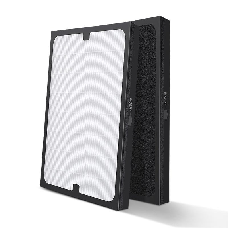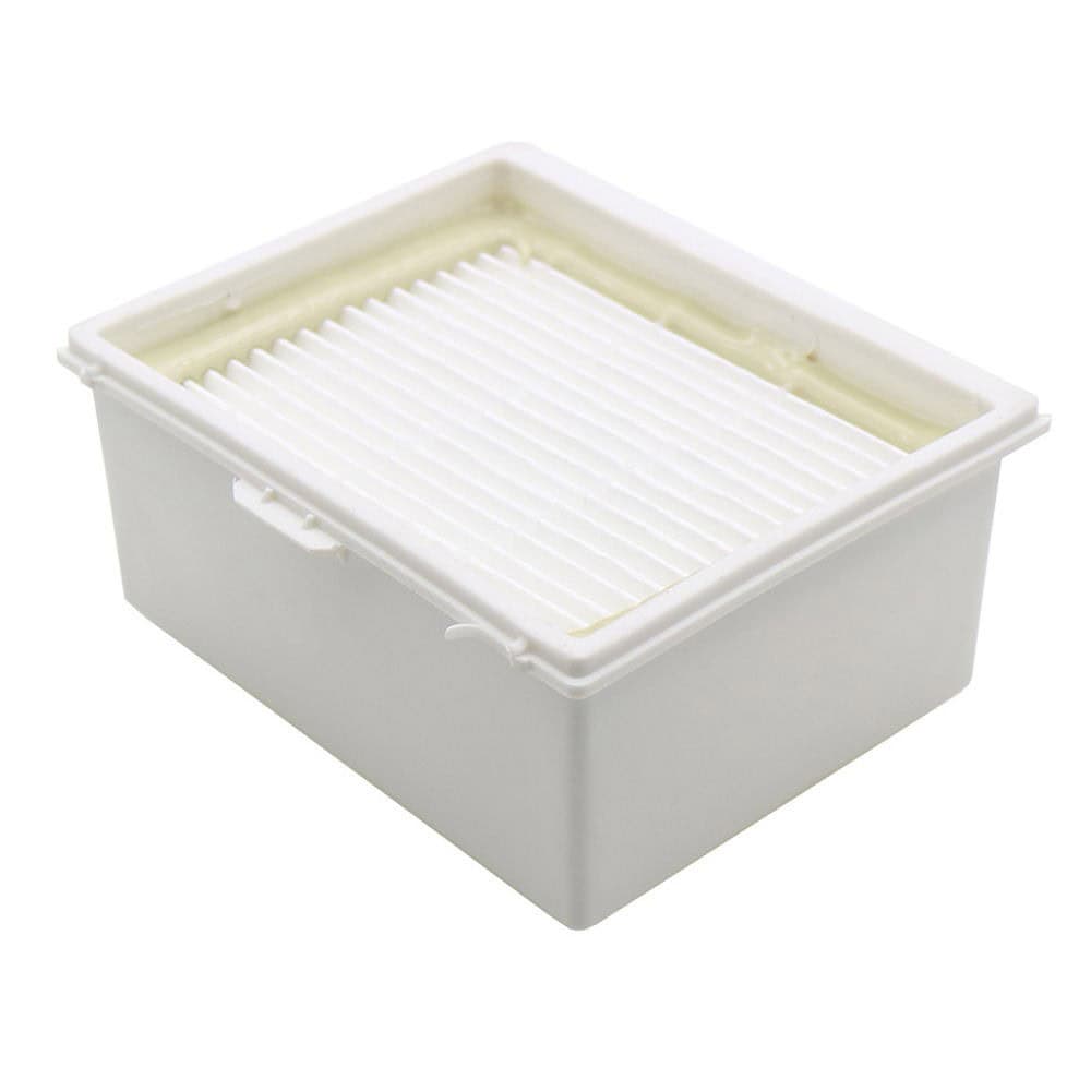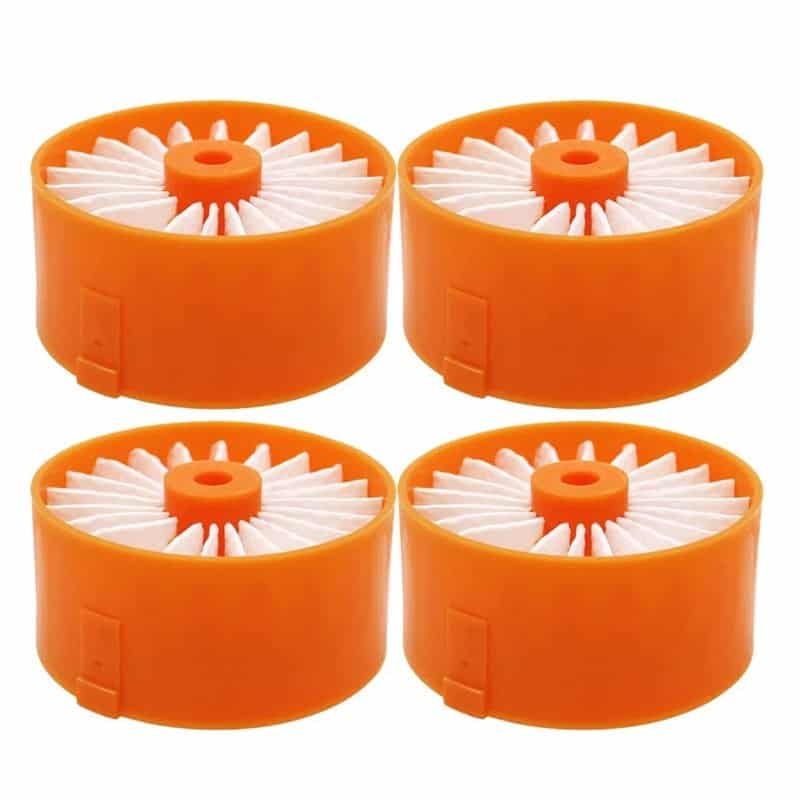
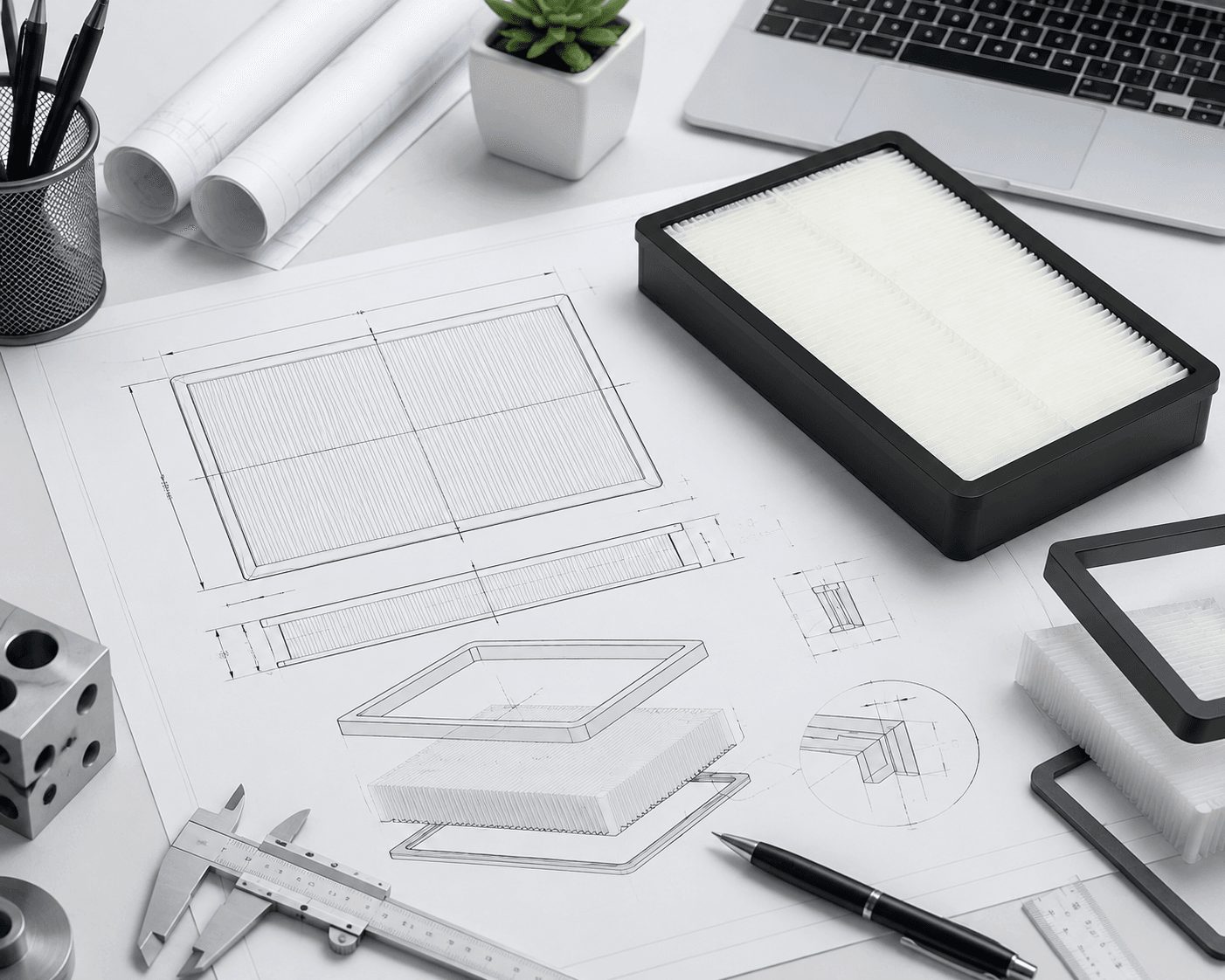
From the outside, a filter might look simple. But an OEM filter drawing has to specify a lot more than the overall shape.
If a filter needs to fit into a specific air purifier, vacuum or other appliance, even small differences in dimensions can affect installation, sealing, air flow and final performance. A clear CAD drawing provides the manufacturer with a fixed reference for quotation, tooling, sampling and mass production.
The aim is to not complicate the drawing. It is to ensure that the manufacturer does not have to guess at critical dimensions or details of construction.
When do I need an OEM filter CAD drawing?
Not every filter project requires a new CAD design. The requirement depends on the degree of difference from an existing filter.
| Project Type | CAD Requirement | Typical Situation |
|---|---|---|
| Existing filter with private label | Usually not required | Existing product with new branding |
| Replacement filter | Helpful | Same design and dimensions as an existing filter |
| Existing design with modifications | Recommended | Changes to dimensions, gasket, or mounting features |
| Custom filter construction | Usually required | New geometry or performance requirements |
| New frame or tooling | Strongly recommended | Custom molded components |
| Completely new filter design | Required | New product developed from a specification |
On an existing product, a physical sample and accurate measurements may be enough to start the engineering review. For new tooling or custom structures a complete drawing is much more important.
If you are still defining the overall OEM project, see our guide to OEM manufacturing.
What Should an OEM Filter CAD Drawing Contain?
The production drawing should fully describe the physical characteristics that affect fit, assembly, and manufacture.
At the very least, check the following:
- Overall dimensions
- Dimensional tolerances
- Filter thickness
- Filter media requirements
- Pleat structure
- Frame material
- Gasket dimensions and position
- Mounting features
- Airflow direction
- Reference points or datums
- Part number
- Drawing revision
- Manufacturing notes
Different projects require different levels of detail, but critical interfaces should always be clearly defined.
What Dimensions Matter Most?
The starting point is the overall size.
For a rectangular filter this usually means:
- Length of time
- Wide
- Height or thickness
For a round cartridge, add
- Outer diameter
- Internal diameter
- Total height
- Size of end cap
The more interesting question is which dimensions govern the actual fit.
Critical Dimensions
These usually deserve extra attention:
- Overall filter thickness
- Frame width and height
- Gasket position
- Gasket thickness
- Mounting tab location
- Clip location
- Hole diameter
- Hole position
- Locking feature location
Do not use notes like “centered” or “same as original” when a feature can be dimensioned accurately.
Instead of saying that a mounting tab is centered, for example, refer to its distance from a defined reference edge.
Why Do Tolerances Matter?
A nominal dimen-sives the target size. A tolerance is the allowable variation.
For example:
240 mm ± 0.5 mm
Not every dimension needs the same tolerance.
| Feature | Importance | Why |
|---|---|---|
| Overall length and width | High | Controls basic fit |
| Filter thickness | High | Affects insertion and sealing |
| Gasket position | High | Helps prevent air bypass |
| Mounting features | High | Controls installation |
| Cosmetic edges | Lower | Usually less important to function |
Don’t make all dimensions unnecessarily tight. Tighter tolerances do not improve actual filter performance, but they do increase tooling and production cost.
The aim is to find out which dimensions are directly affecting fit, sealing, assembly, and function.
Filter Media and Pleat Structure
You will have the physical geometry in a CAD drawing. However, you should also define the filter media and performance requirements.
The term “HEPA filter” alone is normally not enough to specify a complete filter.
The technical specification may need to identify, depending on the application:
- HEPA grade
- Filter media type
- Pre-filter layer
- Activated carbon layer
- Target filtration efficiency
- Airflow requirements
- Pressure drop requirements
For pleated filters, also define the relevant geometry:
- Pleat count
- Pleat depth
- Pleat spacing
- Media area
- Pleat direction
These factors can affect airflow resistance, filtration area, and the final assembled dimensions.
For more information about custom filter development, see our guide to HEPA filter design and custom tooling.
Frame, Gasket, and Mounting Elements
The frame and sealing system are just as important as the filter media.
Frame
Where relevant, specify:
- Material
- Wall thickness
- Overall geometry
- Clips or snap features
- Reinforcement ribs
- Connection points
The manufacturer can determine detailed tooling requirements based on the approved geometry.
Gasket
The drawing should identify:
- Material
- Thickness
- Width
- Position
- Shape
Gasket position is especially important because incorrect placement can create an air bypass path even when the filter media itself is highly efficient.
Mounting Features
Tabs, clips, holes, handles, and notches should be measured from fixed reference points.
For example, a mounting hole should include:
- Hole diameter
- Center position
- Distance from the reference edge
This measurement is particularly important when developing replacement filters for existing appliances.
Our filter compatibility guide explains why an appliance model name alone may not always identify one exact filter configuration.
2D CAD vs 3D Drawing
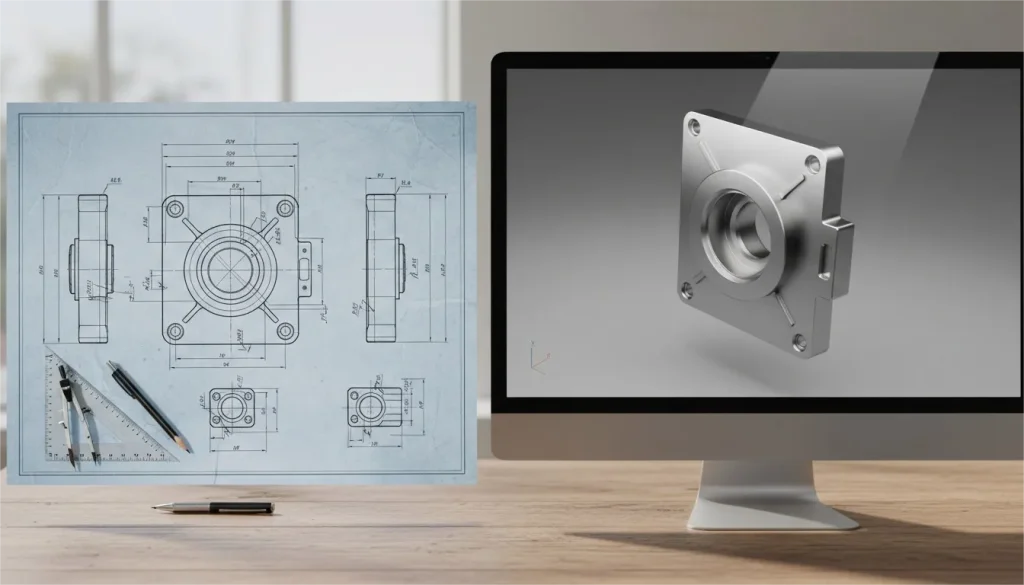
Both formats have a role in OEM filter development.
2D CAD Drawing
A 2D drawing is useful for defining:
- Dimensions
- Tolerances
- Materials
- Section views
- Manufacturing notes
- Reference dimensions
It is often the main document used to control the finished dimensions of the product.
3D CAD Model
A 3D model is particularly useful for custom frames and molded components.
It can help engineers evaluate:
- Overall geometry
- Clips and tabs
- Mounting structures
- Clearances
- Interference
- Tooling requirements
For a simple filter, a fully dimensioned 2D drawing may be sufficient. For a custom molded frame, the manufacturer may request both 2D and 3D files.
What File Formats Should You Send?
Use a format that the manufacturer’s engineering team can work with.
| File Format | Typical Use |
|---|---|
| STEP | 3D CAD exchange and tooling |
| IGES | 3D CAD data exchange |
| DXF | 2D geometry |
| Dimensioned reference drawing |
PDF is great for checking, but it doesn’t give you editable 3D geometry for tooling.
For a custom plastic frame, a STEP file with a dimensioned PDF is often more useful than a product image or a scanned sketch.
Always clearly state the units.
Never leave millimeters and inches guessing.
Drawing Number and Revision Control
OEM projects often go through several engineering changes.
A proper drawing should identify:
- Part number
- Drawing number
- Revision
- Date
- Material
- Units
- Approval status
For example:
Rev A
Initial design
Rev B
Gasket position changed.
Rev C
Mounting clip modified
The latest approved revision must be referenced on the quotation, sample approval, purchase order, and production documents.
This simple step can keep the plant from making an obsolete version of the filter.
How manufacturers are using the CAD drawing
The drawing is used as a reference throughout the production process.
Engineering Review
The manufacturer checks the dimensions, materials, interfaces, and any missing information.
Quotation
The drawing allows the factory to assess the materials, production methods, tooling, and development costs.
Tools Assessment
The manufacturer will be able to tell if the existing tooling can be modified or if new tooling will need to be created.
Development of samples
The approved drawing is then used as a guide for the sample or prototype.
Mass Production
Upon approval, the drawing ensures that future production is in conformity with the approved specification.
OEM Filter CAD Checklist
Before sending your drawing to a manufacturer, check:
- Overall dimensions are clearly shown
- Critical dimensions have tolerances
- Filter thickness is specified
- Filter media requirements are documented
- Pleat structure is defined where necessary
- Frame material is identified
- Gasket dimensions and position are shown
- Mounting features are measured
- Airflow direction is clear
- Units are stated
- File format is confirmed
- Part number is included
- Revision is identified
- Supporting samples or reference parts are listed
The purpose of a CAD drawing is not to make the project look technical. It is to create one controlled reference that both the buyer and manufacturer can use.
Final Check Before Tooling and Production
Before tooling or mass production begins, ensure that the main documents agree:
CAD drawing
Defines the physical dimensions and interfaces.
Filter specification
Defines media and performance requirements.
Approved sample
Confirms that the physical product matches the design.
Packaging specification
Defines branding and retail information.
Purchase order
References the correct quantity and drawing revision.
Keeping these documents aligned reduces the risk of incorrect tooling, failed samples, and production changes.
Partner with an OEM Filter Manufacturer
A good CAD drawing makes OEM filter development easier, but it is only one piece of the engineering process.
HIFINE provides product engineering, filter customization, sampling, testing, tooling evaluation, and production support for air purifier and vacuum filter projects.
Do you have a CAD file, technical drawing, physical sample, or OEM reference? HIFINE’s engineering team will review the information and determine the next steps.
Contact HIFINE for review of your filtration requirements for engineering and quotation. See our OEM and ODM filtration solutions.